


Debug Hardware like the Pros
Simply the world's best logic analyzer. Enjoy on Windows, Mac, or Linux. Pocketsized, 16 channels, fast sampling rate and easy to use software makes this analyzer invaluable on your desk when debugging embedded systems.
| Logic 8 | Logic Pro 8 | Logic Pro 16 | |
|---|---|---|---|
| Channels | 8 | 8 | 16 |
| Digital Sample Rate (max) | 100 MS/s | 500 MS/s | 500 MS/s |
| Analog Sample Rate (max) | 10 MS/s | 50 MS/s | 50 MS/s |
| Interface | USB 2.0 | USB 3.0 | USB 3.0 |
What's included
- Logic Analyzer
- Custom neoprene zippered case
- USB cable
- Test clips (two test clips for every input)
- Test probes
My AutoQuote | Easy & Fast
Easily generate and keep track of your quotes. You can also place an order based on an active quote. Both Quotes and Orders are organized for you under your account page.
More informationSpecifications
| INPUT | |
| Multi-Use (A/D/Both) | 8-16 |
| Input Resistance | 1 M Ohm Pro: 2 M Ohm |
| Input Capacitance | 10 pF |
| Input Protection | ± 25V |
| DIGITAL | |
| Sample Rate (max) | 100 MS/s Pro: 500 MS/s |
| Fastest Digital Signal | 25 MHz Pro: 100 MHz |
| Supported Logic Levels | 1.8 V - 5.5 V Pro: 1.2 V - 5.5 V |
| Works with RS-232, 422/3 | Yes, directly |
| ANALOG | |
| Sample Rate (max) | 10 MS/s Pro: 50 MS/s |
| Bandwidth (-3dB) | 1 MHz Pro: 5 MHz |
| Number of bits | 10 bits Pro: 12 bits |
| Input Voltage Range | 0 V to 5 V Pro: -10 V to 5 V |
| PHYSICAL | |
| Size | 8 Channels: 53 x 53 x 12 mm 16 Channels: 92 x 92 x 15 mm |
| Weight | 8 Channels: 60 g 16 Channels: 220 g |
| USB Type | USB 2.0 Pro: USB 3.0 |
Product information
| Record | To record your digital and analog signals, just press start. You can fill your entire computer’s memory with data so it is easy to capture lengthy or rare events. |
| Setup | Every Logic device can be customized to capture data the way you want. You can select how long to record, specify how bandwidth is allocated between digital and analog recoding, select which channels to record, and even make the LED your favorite color. |
| Navigate | When you have billions of data points to display, it is important that getting around in all that data is a zippy experience. Effortlessly zoom in and out with the scroll wheel, and navigate left and right by dragging the data where you want it. |
| Measure | For basic measurements, just place your mouse near something interesting. The software will figure out the rest and display the relevant measurements. You can show different measurements by right-clicking. |
| Trigger & Find | The software can start recording automatically when it finds a simple pattern you specify. You can trigger on digital edges and pulses as well as analog voltages and pulses. After you collect your data, you can search for more events this way too. |
| SPI, I2C, Serial | Most digital communication uses a particular protocol that specifies how information is transferred. The Logic software has protocol analyzers that can automatically decode SPI, I2C, serial, 1-Wire, UNI/O, I2S/PCM, MP Mode, Manchester, DMX-512, Parallel, JTAGLIN, Atmel SWI, MDIO, BiSS C, HDLC, HDMI CEC, USB 1.1 – and more are on the way! |
| Search | Once you have decoded your data with a protocol analyzer, you can search through all these decoded results by just typing what you are looking for – the software will jump right to the spot where it happened. |
| Annotate | As you dig into your data, you might want to take some notes along the way. In the software you can add unlimited bookmarks, which remember what you were looking at; timing markers, which can measure the time between events; measurements, which annotate the waveform with parameters like width, frequency, RMS voltage and duty cycle; and, of course, your notes. |
| Save & Share | Once you’ve annotated your data, you can easily save it for later review. You can even save it in the cloud to send to colleagues or post online! |
| Export | Sometimes you will need to do something pretty custom with your data, so you’ll be happy to know it is easy to export it in a variety of formats, including a text csv file or Matlab m file. |
| Automate | If you need to automate the Logic software, you can control everything over a simple TCP socket using virtually any programming language. |
| SDK | Have a rare or proprietary protocol you would like to have Logic decode? You can with our Analyzer SDK. |
| Craftsmanship | We really care about this stuff. And we think that when you get Logic in your hands, you’ll be able to tell. |
| Machined Aluminum | Every Logic starts as extruded 6061 T6 aluminum plate. It is then precisely machined with a 3-axis CNC mill, using four different setups and seven different solid carbide tools. |
| Metal Finishing | The machined enclosure is cleaned and then textured with a light glass bead blast to give it a uniform, elegant look. Next the part is anodized, brightened, colored and sealed. This is the finish quality you would expect from pro-audio equipment or a new MacBook. |
| RGB LED | Choose your favorite color to customize your Logic. The brightness is controlled by PWM, and we’ve RC-filtered the PWM so the LED does not contribute any measurable degradation to your signals. |
| Low-jitter | The low jitter of the ADC sampling clock assures the SNR is not degraded. |
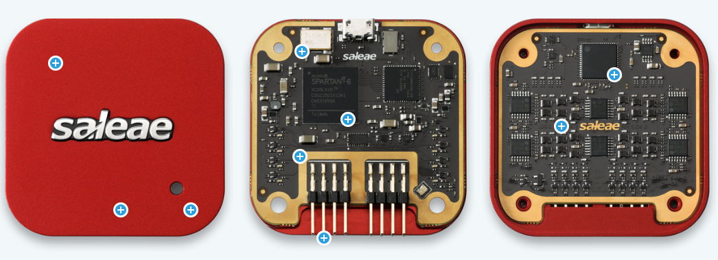
| FPGA | Logic 8, Logic Pro 8 and Logic Pro 16 feature the Xilinx Spartan 6 FPGA, which interfaces to the ADC, digital inputs, and USB bridge. The FPGA also has the capability of performing over 5 billion DSP operations per second (over 10 billion on Pro 16). When you use more analog channels than can be streamed over USB at once, we need to filter and decimate that data in the FPGA – reducing the bandwidth without introducing aliasing. Logic Pro 16 produces analog data at a rate of 9.6Gbit – that’s a lot of data to process in real time! |
| PCB | PCB assembly is performed by our assembly partners in Fremont, California. Logic 4 is 6-layer, Logic 8 is 8-layer, Logic Pro 8 and 16 have, well, more layers than that. |
| Dual-Use Inputs and Signal Integrity | To provide optimal signal integrity with a flying lead test probe, each input has a dedicated ground wire. In most situations, users can leave extra grounds disconnected. In addition, on Logic 8, Logic Pro 8, and Logic Pro 16, each input can be configured to be an analog input, a digital input, or both at the same time. Logic 4 has one input which is both analog and digital, while the remaining three are digital only. |
| ADC | Logic 8, Pro 8, and Pro 16 all have 8-channel ADCs. (Pro 16 has two.) Logic 8 has an analog sample rate of 10MS/s at 10-bits, and Logic Pro 8 and Pro 16 sample at 50MS/s at 12-bits. For Logic Pro 16, this is an awesome 9.6Gbit of data which must be handled by the FPGA. When you use more channels than USB can handle, the FPGA filters and decimates the data in real time so that the resulting signal does not exhibit any aliasing from frequencies above the new bandwidth. |
| Anti-aliasing Filters | An anti-aliasing filter prevents frequencies higher than the Nyquist frequency from being sampled. Any frequency content higher than Nyquist will result in aliasing, which, generally speaking, makes it impossible to compute an accurate FFT. Filters can have an adverse effect on both gain and phase so this must be carefully accounted for. |


